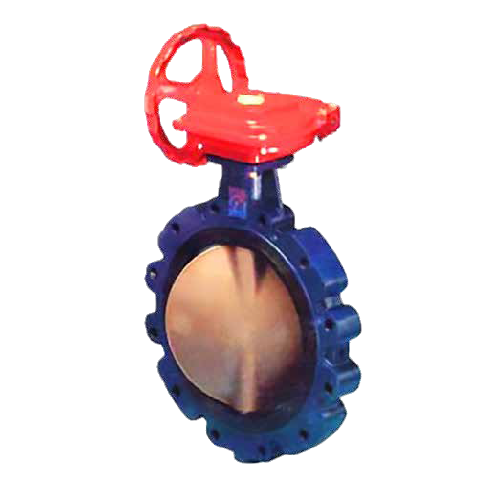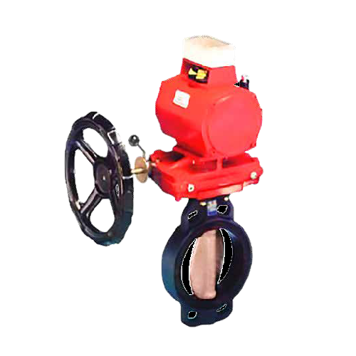


Description
Alpine Wafer Lugged Butterfly Valve

Applications:
• This design has been used in the most difficult applications and where long life is expected.
• Water reticulation
• Low-pressure steam
• HVAC
• Mining: water and air
• Marine applications
• Sea water applications
INTERNAL DISC TO STEM CONNECTION
Alpine has square machined flats on the stem and in the disc. The non-wetted connections eliminate exposed external disc to stem connections. The disc and the stem connection minimize any play and result in secure fitment. Stem design incorporates a blowout-proof feature.
SEAT DESIGN
The seat is designed to seal with slip-on or weld-neck flanges and the molded o-ring eliminates the need for flange gaskets. The tongue and groove lock the seat in place and makes the valve capable of “dead-end” service. This resilient seated butterfly valve provides both a primary and secondary seal between the disc and seat as well as the stem and seat which ensures the total encapsulation of the line media and zero external leakage.
NOTES:
• Flange accommodation must be specified when ordering.
• Specify size, product name, part name, material, and flange accommodation when ordering spare parts.
• C = FTF ISO 5752 series 20 – NF E 29305 series 20 – MSS SP 67 – API 609 – DIN 3202 – BS 5155 – EN 558 (excl. DN350).
• Outside dimensions of the shafts are standard.
• For other valve sizes, see specific datasheets.
• (øG*) Ultra standard is square shafts for DN50-DN800, key drive for DN850-DN1000. Key drive for DN250-DN800 are available on request.
• 1 bar = 14.6 Psi